


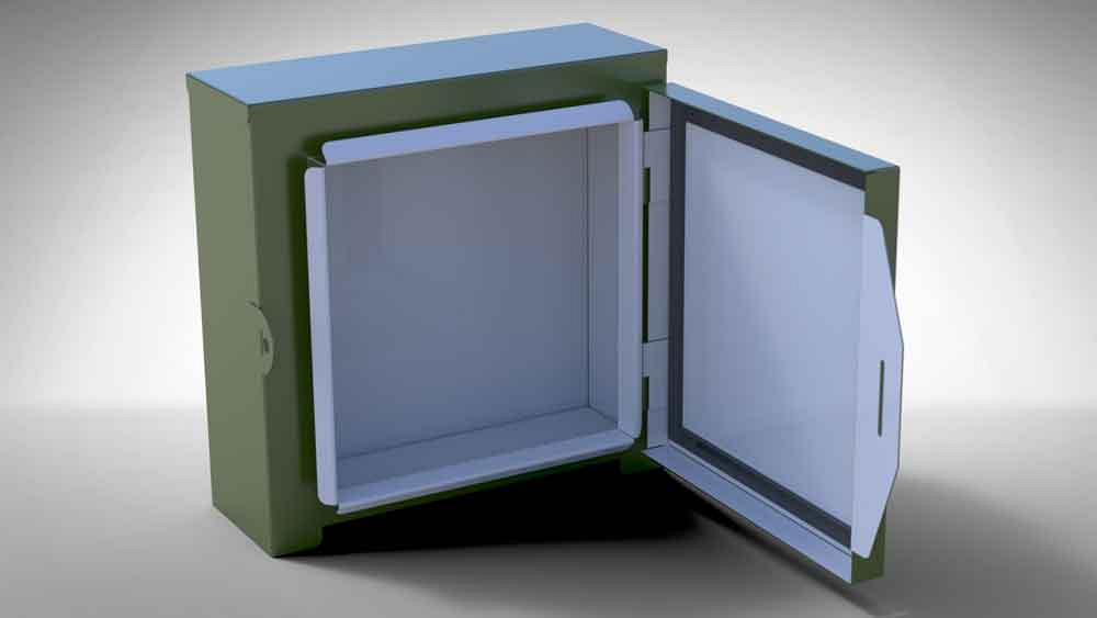
Figure 1
The model for this sheet metal enclosure allows for free-swing mouse-drag of the door and the generation of 2D drawings for fabrication.
The previous episode revolved around a billet—an off-the-shelf standpipe that yielded two finished parts by merely cutting it in half. The documentation allowed for confusion regarding who was to purchase the billet and how many billets were needed. Because of the miscommunication, too many finished items ended up in inventory. Whether parts are custom-made or purchased ready-made, clarity regarding quantity and source is vital.
If your preferred CAD system avoids the problems discussed or you have better solutions in any way, please let us read about it.
This episode embraces the idea of using a vendor-provided model for a purchased item. A downloaded model may require some massaging before it satisfies all design goals. In some circumstances, modeling from scratch might be a better starting point than extensively editing a download.
But that’s enough with the disclaimers. Let’s get to it.
Two Tone in Olive Drab
Figure 1a is a visualization of our design for a painted sheet metal enclosure. One of the subtle mechanical features of the design is good water shedding. The roof overhangs the side walls while the walls overhang the floor. This splash-resistant box features a gasketed door with a snap-hasp that gently latches the door closed (see Figure 1b), along with an eyelet for optional security. It is suitable for spot welding, maybe riveting.
This hinged box was modeled with the idea of easy editing to create variations in size. We are not aware of any patent or design restriction on this generic enclosure. We are using it for illustration. If you use this download as inspiration in your product line, check with prevailing patented art. And please make ongoing contributions to sustain the FMA. The download shows a few tricks regarding configurations that are glossed over in this discussion.
Details of the door closure and lift-off are shown in Figure 2. As intended function, the hinges allow the door to be completely removed from the box. The door will not lift off when it is closed. One must fully open the door for the door’s bottom flange to clear the box rim and then lift to separate the hinges.
Here is some foreshadowing: A CAD technique is available that allows a leaf welded to the door to travel with the door and a leaf welded to the box to remain stationary. This may require four visible hinge pieces associated with a single part number in a quantity of two.
Swing Versus BOM
To present this design to a review audience, you should make the door swing realistically on its hinges with a mouse-drag. For documentation of the product for fabrication, the bill of materials (BOM) should show that a single part number obtains both leaves.
As a review of various modeling techniques, versions of a purchased hinge are shown in Figure 3. The multibody model in the bottom-center of the illustration started out as a download and import of a STEP file.
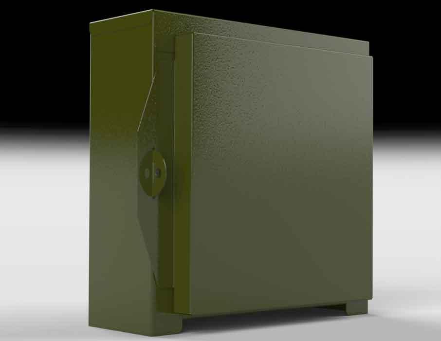
Figure 1a
This view of the sheet metal enclosure model shows the box closed.
The imported vendor’s CAD—shown as a flat hinge in Figure 3—is rigid but features correct bodies for the leaves of the hinge. CAD tools are available for fixed positioning of bodies in a multi-body model.
For purposes of posing the model, multibody parts can be useful. When configurations with its bodies in different positions are created, the multi-body hinge part can be used to quickly create static images, such as door open or door closed.
When a mouse-drag swing is required, an assembly is a good modeling technique. CAD software makes it easy to create separate files from multibody models and then use those parts as components in an animated assembly.
In Figure 2 the leaf bodies split from the imported CAD are shown in the upper left corner. Those parts were used to model a mouse-draggable assembly shown in the upper right of Figure 2. Mates in that assembly limit the open/closed angle and the lift-off distance of the leaves.
Auto-BOM Splat
We use splat as colloquial for the asterisk symbol. CAD software uses asterisks instead of digits when it feels confused. When a balloon is attached to a body that has no row in the balloon’s BOM table, the balloon displays an asterisk instead of a number. Components intended only for visualization can be set to exclude them from the assembly’s BOM.
There are several sources of splats. A view may be attached to a BOM table other than the BOM table you expect it to be attached to, usually as an unintended consequence of using configurations instead of display states to create step-by-step illustrations. But that’s a topic for another episode. A wrong BOM table linkage or wrong configuration selected for the view is likely to result in balloons with unexpected item numbers, including numerous splats.
Figure 4 shows four examples of splatted balloons. They are attached to itemless bodies. These four hinge leaf bodies exist only for the purposes of visualization and mouse-drags. In this example, they have settings to exclude them from the BOM, thus causing the splats.
As an example of problematic CAD jockey behavior, included in the BOM is Item 1—the purchased lift-off hinge. That entry in the BOM table is the result of an invisible model. That component model is included in the assembly just to contain product manufacturing information (PMI). The invisible BOM-populator model is patterned to get the quantity right.
The problem with this mediocre solution is that balloons are hard to attach to invisible bodies. A CAD jockey has the power to edit the balloon and manually substitute the correct digit, sort of like editing the value of a dimension without changing the geometry. That is a sin and should cause shame. Bad CAD jockey.
Several honorable solutions can be used to address this dilemma. All involve making a visible body that is the sole carrier of PMI for all the pieces associated with the item. That may seem to be pretty intense CAD-speak, but try this: As a possible solution using configurations, you can show various bodies in a multibody part, give the bodies part numbers, and position them in 3D space—all in a single file. Aren’t multi-body parts swell?
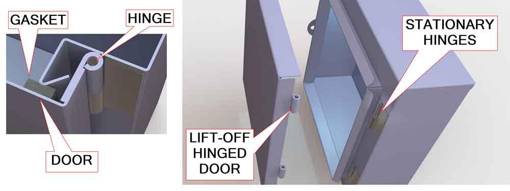

Figure 2
To the left we see the closed door’s gasket sealing against the rim of the box. The door is held in place by two hinges and a snap-hasp.
Invisible Body Idea Vanishes
Without using multibody components, a pretty good solution to the dreaded auto-BOM-splat is revealed in Figure 5. If we make an assembly of all the pieces associated with the BOM item—in this case two hinge leaves—the item number for the BOM table is automatic and intuitive.
To visualize the two leaves as separate items in the exploded view in Figure 5, we use the Exploded-View CAD tool to position the components of the hinge subassembly. That’s another CAD setting that sounds almost like plain talk. The same trick—positioning components in the illustration with the Exploded-View tool—was used to set up the door lift-off shown in Figure 2. This assembly has more than one exploded view.
In this project almost all the items in the product are contained in a single assembly. The exception is the hinge leaves. They are now in a subassembly for our BOM and animation convenience.
To allow for mouse-swing/kinematic motion, the hinge assembly is made flexible, another CAD setting. As the hinge assembly was modeled, limiting mates were included. Those mates apply even when the subassembly is made flexible. Thus, the mouse-drag to open/close the door is reasonably realistic, albeit frictionless.
The problem with this CAD technique (all components in one assembly except for the hinge) is that simulating the door removal, as in Figure 2, is not easy to model. To make door-removal-by-mouse easy, the door could become a subassembly with half of the hinge, and the box could become another assembly with the other half of the hinge. By mating these assemblies, perhaps with a path mate, we could simulate the motion of pivot, lift, and removal with a mouse-drag or motion study.
With two subassemblies, the hinge pieces would appear in two BOM tables. From each BOM, one part number still obtains both leaves, so whoever welds the door will end up with extra hinge parts. It’s the same with the box. One could put a note on the drawing for the box that it has to be made in conjunction with the door, so you don’t buy too many hinges. In the worst case, stock the extra hinges with last month’s standpipes. You will probably end up with matched sets.
Gerald Davis would love for you to send him your comments and questions. You are not alone, and the problems you face often are shared by others. Share the grief, and perhaps we will all share in the joy of finding answers. Please send your questions and comments to [email protected].
Recent Comments